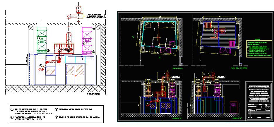
Figure: From left to right, section view and planimetry of the ICEs laboratory
● Soundproof cabinet (guaranteed noise reduction of 40 dB (+/- 2 dB)) made by prefabricated panels and metal superstructure of 7.2 m x 5.0 m x 3.0 mm.
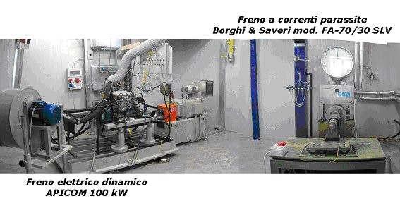
● Dynamic electric brake APICOM of 100 kW: three-phase synchronous generator of 380 V – electric current of 380 A (rated operating condition), with a maximum of 450 A – maximum rotational speed of 7500 rpm (forced air cooling)
● Air handling unit of 1000 m3/h with controllable temperature (20-25 °C) and humidity (45-60 %)
● Forced air ventilation with intake and extraction fans capable of elaborating flow rates up to 15,000 m3/h
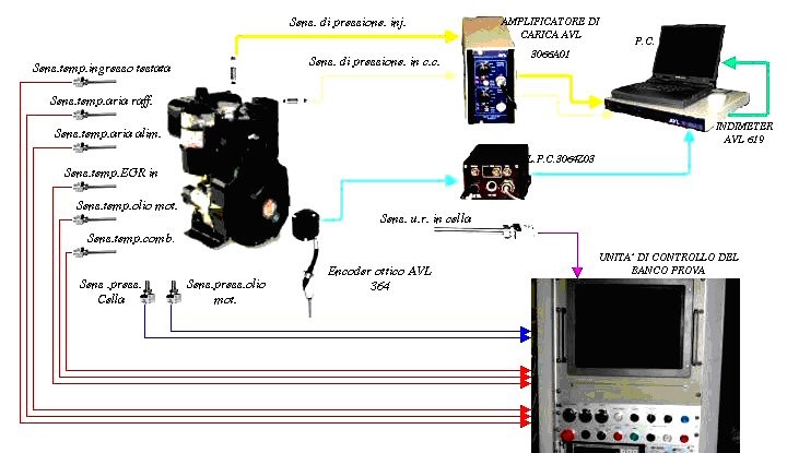
● Detection system of the engine cycle (AVL Indimiter 619)
IMAGES FOR ENGINE ACTIVITIES
DIESEL ENGINE POWER SUPPLY D.I. WITH DIESEL-BIODIESEL MIXTURES
Experimentation on Ruggerini RF91 single-cylinder diesel engine with direct injection (Pmax = 8Kw at 3600 rpm) air-cooled.
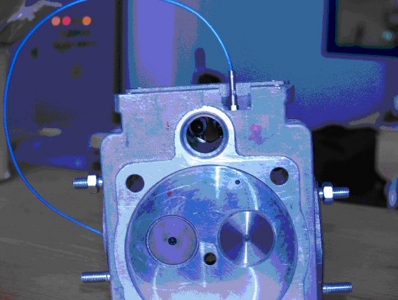
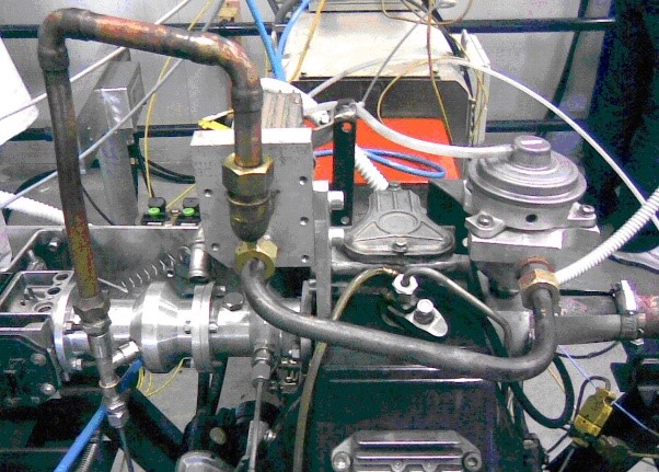
Circuit of the EGR DC pressure sensor installation
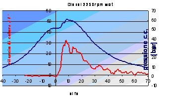
Trends in DC pressure (blue curve) and heat release (red curve).
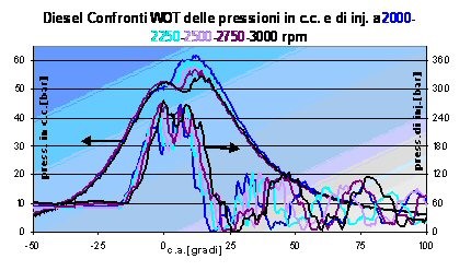
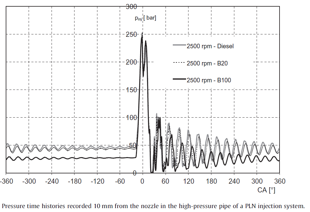
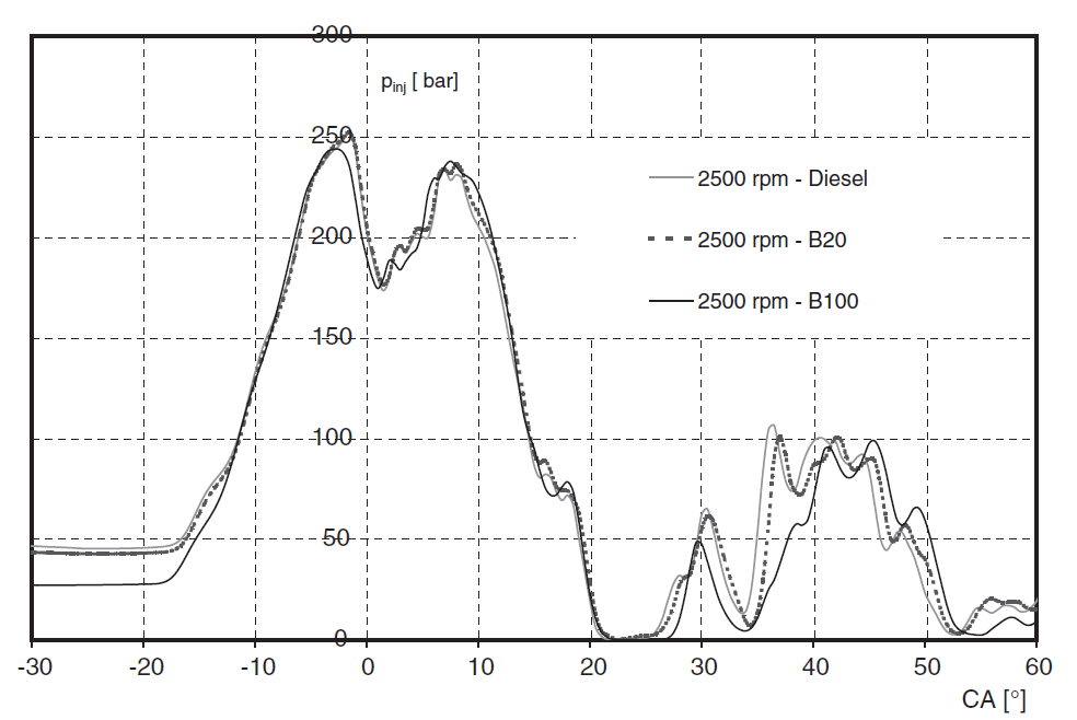
Pressures in the combustion and injection chamber as the speed changes.
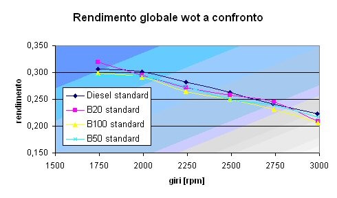
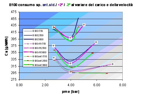
Comparison of WOT yields and specific consumption with changes in load and speed.
INJECTION SYSTEM SIMULATIONS
STUDY OF ADVANCED COOLING SYSTEMS FOR M.C.I. (THERMOMANAGEMENT)
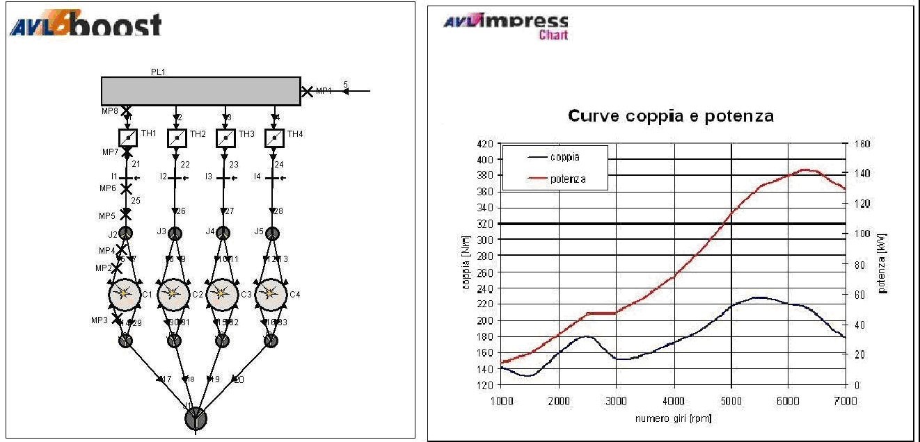
AVL-Boost model of the engine and its performance
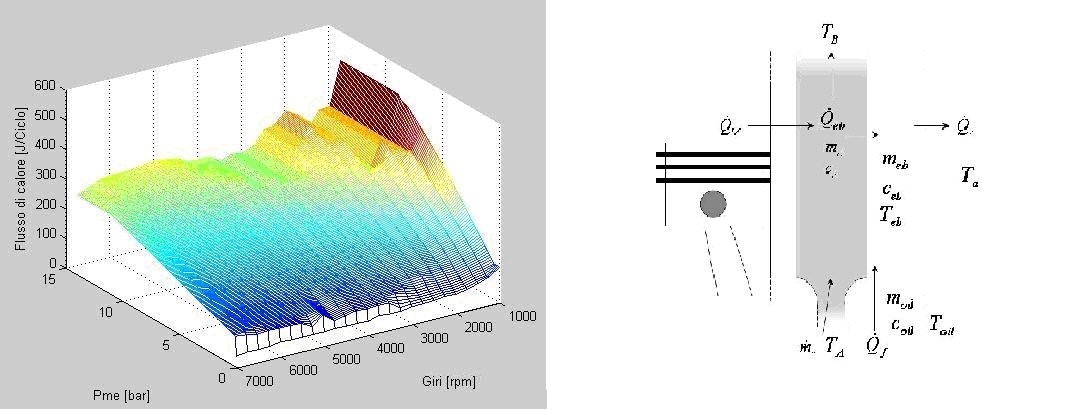
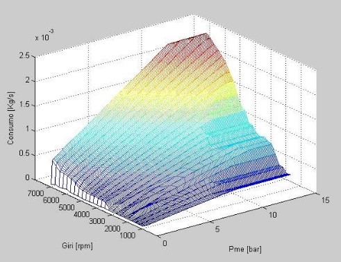
Mapping of fuel consumption and Mapping of heat flow to the refrigerant
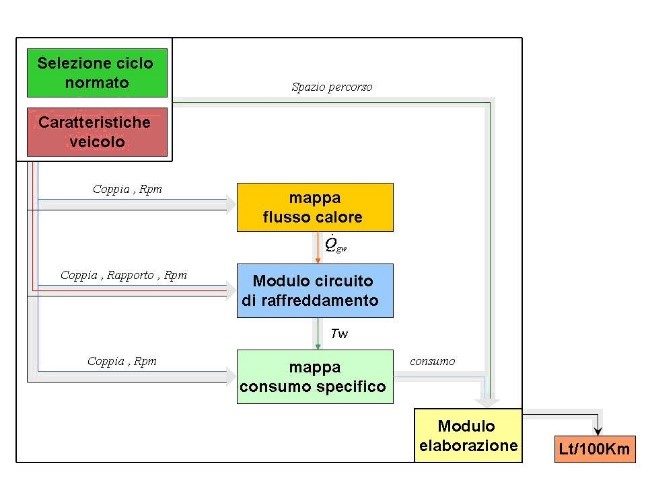
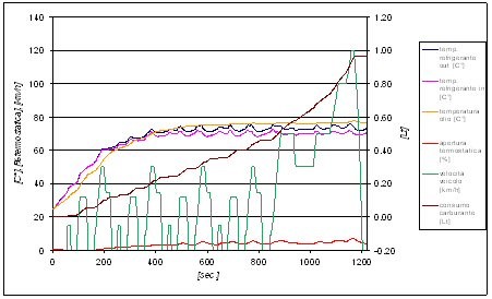
Example of simulation results for ECE – NEDC cycle