The study mainly concerns the solid state welding technique, called Friction Stir Welding (FSW), for the joining of similar and dissimilar metal sheets obtained either by a numerical control center or by a robotic system. This process is based on friction heating and mixing carried out by means of a rotating tool around its own axis, inserted between the edges of the sheets to be welded. The combined effect of rotation and translation of the tool along the welding line allows the obtaining of the joint. The material flow is characterized by an intense plastic deformation at high temperature (always lower than the value of the melting temperature) and by the consequent generation of a very complex microstructure which significantly affects the properties of the joint and depends on the geometry of the tool and the process parameters used.
The approach followed in the study of the FSW is based on the analysis of the relationship between the process parameters (such as the geometry and tilt angle, the tool sinking, the rotational and welding speeds), and the properties of the welded joint, such as mechanical strength and ductility, in order to identify the optimal welding conditions. In this framework, both experimental techniques and numerical simulation methods were used with the aim of developing prediction models of the mechanical properties of the welded joint.
The research activities carried out in the field of the FSW concerned the following aspects:

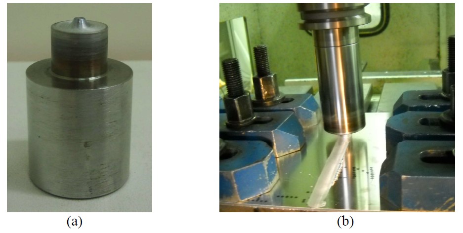
Tool used in friction stir welding and friction stir welding process

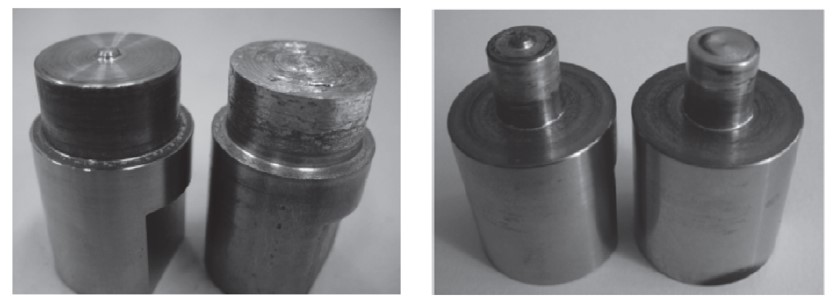
Pin and pinless tool configurations

Cold stamped parts obtained by placing the FSWed sheets with the welding line (a) parallel, and (b) perpendicular to the short side of the die

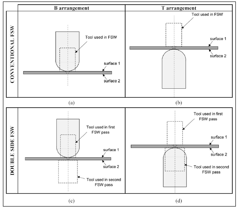
Different sample arrangements for hemispherical punch tests. B arrangement: ‘‘surface 1’’ in contact with the punch. T arrangement: ‘‘surface 1’’ countered with the punch

Thermograph of similar joint in AA6082 in three position of the welding tool (15, 90 and 165 mm respectively from welding start) (1500 rpm; 60 mm/min).

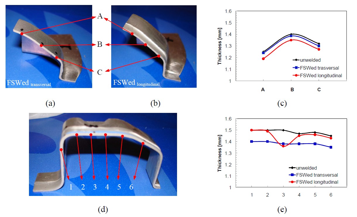
Regions of the stamped component and sheet thickness distribution: (a), (b) and (c) critical region, (d) and (e) central region
